Hardware reference
Overview
A top-down overview of the system, indicating the respective roles of the components, is shown below:
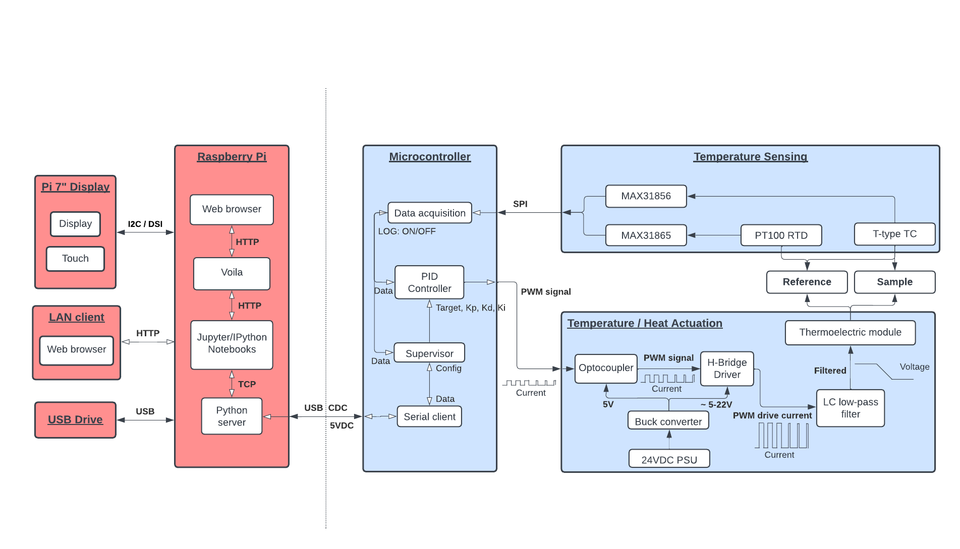
The left side of the diagram shows the components associated with high-level system functions, such as:
Displaying information and receiving user input
Defining heating programmes, based on user input and initiating/stopping these based on user commands
Communicating with the microcontroller program, updating it with the appropriate programed parameters and receiving sensor data sent by it.
The right side of the diagram shows the components associated with the low-level integration of electronics components and control processes, such as:
Reading values from attached temperature sensors
Regulating heat output of the thermoelectric module, based on parameters specified by the current heating programme, as well as the current temperature readings
Communicating with the web app program running on the Raspberry Pi, sending temperature data as requested and receiving parameters related to the heating programme.
Electronics
Temperature Sensors
As previously shown in components, the temperature sensors that can be used with the system include restistance temperature detectors (RTDs) or thermocouples.
For absolute temperature measurements, the details of how RTDs and thermocouples function, and their differences are not particularly important. In general, RTDs will achieve greater precision, up to 0.1 degrees Celsius, compared to thermocouples, which are typically limited to approximately 0.5 degrees Celsius precision - however, these will be subject to the specific type of RTD/thermocouple used.
However, in the case of differential temperature measurements, thermocouple temperature sensors are able to provide a unique advantage over RTDs, due to their ability to be wired in a ‘differential’ setup, as shown below:
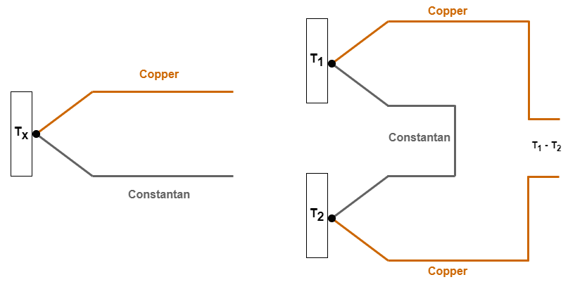
The voltage produced at the open terminals of the differentially wired thermocouple is approximately proportional [1] to the difference in temperature between the two probes [2] . For sufficiently high-resolution voltage sensors, this can allow a differential thermocouple to achieve precision in the tens of mK.
Because the temperature-dependent voltage values produced by the sensors is typically very small (in the mV, or less), the use of amplification, or high-resolution voltage sensors (or both) is necessary to extract the temperature readings.
Unsurprisingly, integrated chips providing exactly these features are available, such as Analog’s MAX31865 (RTD) and MAX31856 (Thermocouple) products. These ICs both feature high-resolution ADCs, precision voltage/current references, built-in amplification and SPI communication, allowing them to be easily integrated with a microcontroller over the SPI bus.
The Adafruit breakout boards used for the system integrate these ICs, allowing any combination of up to 4 RTDs/Thermocouples to be used for temperature measurements.
Temperature Actuators
The temperature control of the sample and reference is handled with the use of a thermoelectric module (TEM). This is a type of solid state device, which acts like a heat pump, in response to an applied electrical current - heating on one side, whilst cooling on the other.
This heat pump effect can be reversed by reversing the direction of the electric curent, causing the previously heated side to cool and vice versa. This allows TEMs to achieve very precise temperature control, by applying corrective heating/cooling to an attached object, in order to maintain a target temperature.
In order to apply the reversible current needed to drive the TEM, an electronic circuit called a H-Bridge is used, consisting of four switching transistors, which selectively allow current to flow in one direction, or the opposing one, based on the input applied to their control terminals (e.g voltage applied to the gate terminal, in the case of MOSFET transistors).
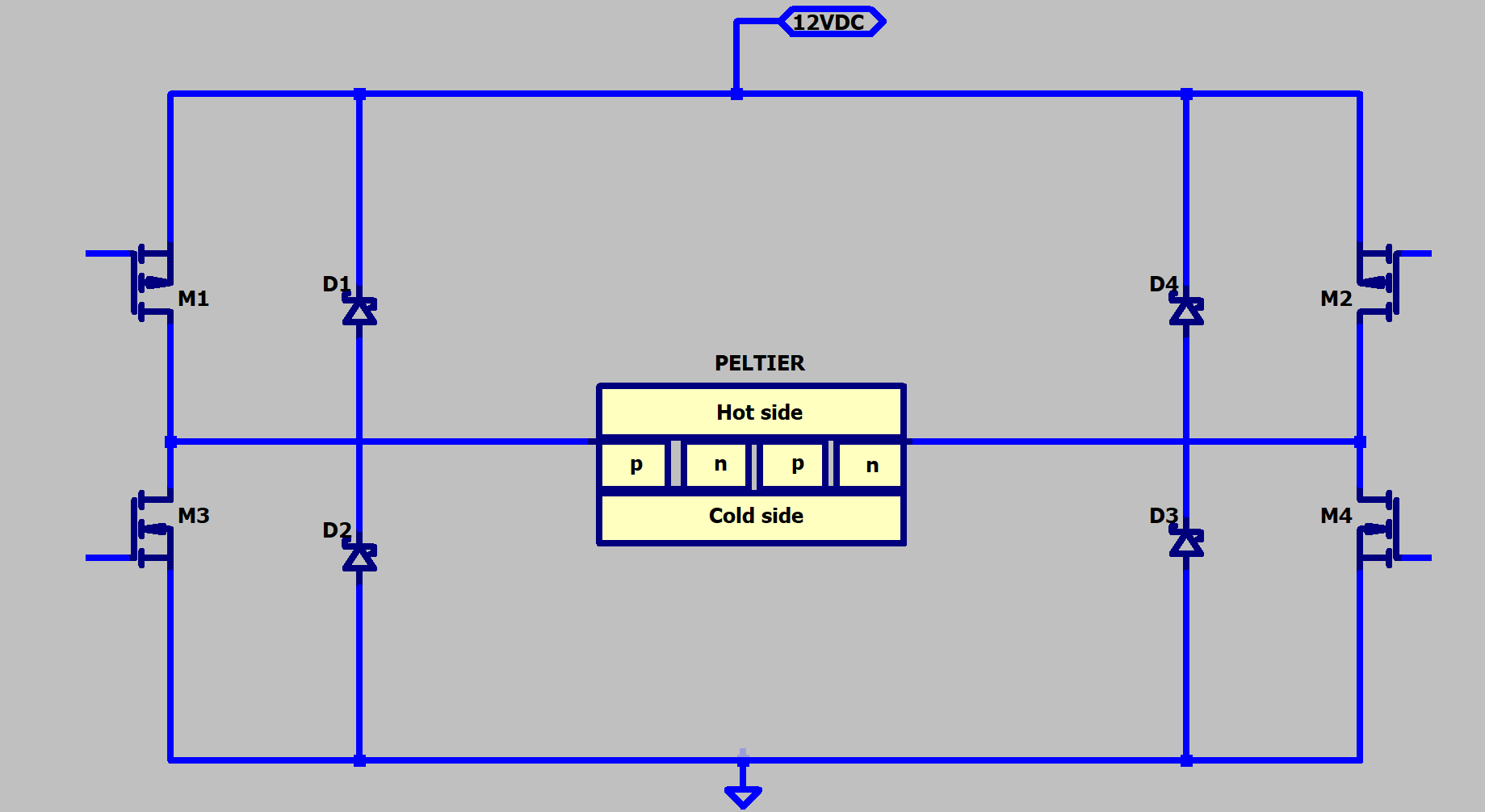
This type of circuit is often used to drive reversible electronic loads, such as brushless DC motors, or speakers - typically with the use of a pulse-width modulated (PWM) signal to control the switching of the MOSFETs. These very common usecases mean that existing implementations of H-Bridge circuits are both plentiful and relatively cheap, allowing off-the-shelf parts, like the HAT MDD10A to be used for our purposes.
Additional care is needed in the case of TEMs when it comes to PWM control, however, due to issues such as thermal cylcing [3] and reduced efficiency [4] . For these reasons, a low-pass LC filter is used, as shown below, to smooth the PWM output of the H-Bridge, which is present on the Thermoelectric module interface board.

Footnotes