Microcontroller software reference
Introduction
In line with the project aim to provide a python-based implementation that is relevant to a wide audience, the software developed for the microcontroller uses CircuitPython, a derivative of MicroPython <https://docs.micropython.org/en/latest/>`_.
The reason for adopting CircuitPython over MicroPython was its built-in support for USB-CDC. This feature allows a microcontroller that is connected to a computer via USB to simultaneously provide serial communication between the python code running on the microcontroller and computer, in addition to mass storage, allowing the microcontroller’s python code to be updated easily.
In combination with the MicroPython REPL prompt, this provides a very user friendly, familiar environment for Python programmers to engage in microcontroller programming.
Overview
The high-level behaviour of the microcontroller is shown in the following picture:
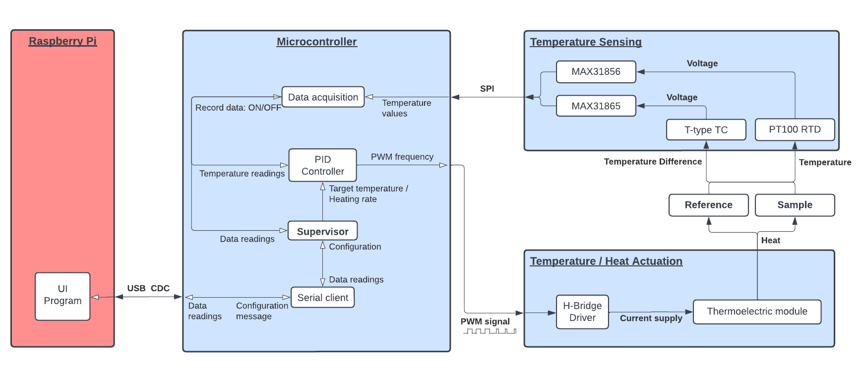
Components
Focusing on the MCU, we can see that it is involved with three primary interactions:
Data aquisition: The MCU interacts with the temperature sensing components, consisting of:
the physical temperature measuring sensors themselves (RTD/Thermocouple), which are connected to
the integrated chips (MAX31865/56) used to convert the voltages produced by the sensors into digital temperature readings.
The communication between the MCU and ICs is carried out over the SPI bus.
PID Control: As described in the Temperature Actuators section, the heat output of the thermoelectric module is controlled by a H-Bridge electronic circuit. This H-Bridge driver takes two control input signals:
A PWM signal, controlling the magnitude of current supplied to the thermoelectric module (and thus quantity of heat pumped by the module), as well as
A HIGH/LOW direction signal, controlling the polarity of the current as +ve or -ve (and therefore direction of heat pumping i.e cooling or heating)
The MCU adjusts these two signals using a PID control loop, which takes into account the specified temperature or heat rate provided by the user and actual measured temperature or heat rate, adjusting the control signals so that the measured values move towards the target values.
Serial communication with Raspberry Pi: Because control of the system is done via the user interface program running on the Raspberry Pi, when a user carries out any command such as
specifying a target temperature or heat rate,
initiating/stopping a heating run,
modifying system parameters such as the PID gain,
this information needs to be communicated from the Pi to the MCU. This is done via “configuration messages”, which are sent over a serial connection from the Pi to the MCU. The same connection is also used to send the temperature readings captured by the MCU back to the Pi, which are displayed on the temperature-time chart of the UI.
Supervisor
In practice, the specific details of the interactions described above do not stay fixed. Consider the following examples:
When the system is idle (i.e not carrying out a heating run), the PID controller’s output should be switched off, to prevent the thermoelectric module from heating the sample and reference. The MCU should still capture temperature data, as the UI program running on the Pi will need to know the starting temperature for a heating run, however these temperature readings do not need to be timestamped and can be updated relatively infrequently.
When the system is active, the PID controller’s output needs to be enabled. When capturing temperature data, the MCU must timestamp this, referenced to the time the heating run started, so that the heating rates can be verified later on.
As was discussed in the Programme tab section, heating runs consist of individual heating stages, which have two parts, a heating ramp and a hold period. The former consists of a constant heat rate temperature increase up to a target temperature, whilst the latter involves holding the temperature constant at the target temperature for a given hold time.
The method used by the PID controller to determine the value of its output control signal will need to change, depending on whether it is controlling a heat ramp or hold period.
This variable behaviour explains the need for configuration messages, passed from the Raspberry Pi to the MCU, which allow it to carry out the correct behaviour that matches the state of the UI program.
These configuration messages are parsed by a Supervisor on the MCU, which is responsible for keeping the microcontroller state (or “configuration”) in sync with that of the UI program on the Raspberry Pi.
Program Structure:
The basic logical structure of the microcontroller python code is therefore illustrated below:

Component classes
Looking at the three (orange shaded) Component classes, the three interactions discussed above form the basis for three program classes, with each class handling one of the interactions.
log - handles logging of data, such as temperature values, time, etc.
PID - handles temperature control, using a PID control loop
client - handles serial communication with UI program running on the Raspberry Pi
All three classes adopt a similar interface, in the form of their update() methods, which, when called, will handle the tasks detailed above.
Supervisor classes
The (green shaded) Supervisor class adopts the three component objects when it’s created,
(main.py)
28class Supervisor:
29    """
30    ...
31    """
32 def __init__(self, serial_client, PID, log):
33
34     self.components = [serial_client, PID, log]
35     self.client = serial_client
103thisSupervisor = Supervisor(thisClient, thisPid, thisLog)
calling their update() methods, as part of its run() routine.
83def run(self):
84    _ = [component.update() for component in self.components]
85    self.pull_config()
86    self.push_data()
The other two routines on lines 85 and 86 are used for the following:
pull_config()involves theSupervisorinstance reading any configuration messages sent to the MCU by the Pi and adjusting the correspondingconfig`parameters for each of the three componentspush_data()involves theSupervisor‘popping’ data from theLogcomponent and sending it to the Pi.
Sensor classes
The class Sensor basically functions as a wrapper class for the
different data readings that the MCU captures.
Wrapper classes essentially take existing programming classes and “wrap” them in a common interface, so that the same functions can be called on all of them.
The Sensor class simply provides a common read() method, which
allows the Log and PIDState classes to treat data generating
objects in the same manner:
30class TempSensor(Sensor)
31
32...
33
34def read(self):
35   return round(self.device.temperature, self.precision)
40class TimeSensor(Sensor)
41
42...
43
44def read(self):
45   return self.time
For example, when the Log class - which takes Sensor type objects
when its created, in much the same way the Supervisor class takes
component classes - has its update() method called, this is what happens
underneath:
73def update(self):
74
75...
76
77for nth_sensor in self.sensors:
78   self.readings[nth_sensor].append(self.sensors[nth_sensor].read())
In summary, the Sensor class basically just provides a modular way to
treat potential data sources such as temperature sensors, time-stamping etc.
This would be equally applicable for other potential data sources, such as
the MCU’s ADC etc.
Configuration Messages
As discussed above, configuration messages are passed from the Pi to the MCU in order to change the behaviour of some of the component classes, in response to the user’s use of the system.
The actual format of the configuration messages is UTF-8 byte-encoded string representations of Python dictionaries, where the following key:value pairs can be used:
CONFIG = {
   'RUN'       : False, # Specifies system idle / active
   'MODE'      : False, # Specifies heat ramp / temp hold mode
   'LOG'       : False, # Initiates time-stamping when enabled
   'TARGET'    : 23,    # Target heat rate / target temperature
   'KP'        : 35.0,  # Proportional gain for PID control loop
   'KD'        : 2.0,   # Derivative gain for PID control loop
   'KI'        : 3.5,   # Integral gain for PID control loop
   'INTERVAL'  : 0.25   # Time interval between successive readings (s)
   }